

Originally published in the Slide Rule Gazette, Issue 11, Autumn 2010
Illustrations courtesy Peter Fox
Illustrations courtesy Peter Fox
In Issue 10 of the Slide Rule Gazette I wrote an article on Hudson’s Computing Scales. I was able to describe the Pump Duty Computing Scale and the Horsepower Computing Scale in some detail, but the other two scales I had very little information on. Whilst that is still the case for the Photo Exposure Scale, I am now able to describe the Shaft, Beam & Girder Scale in more detail thanks to Peter Fox who has kindly supplied me with scans of a card example that he has recently obtained.
In the 1912 W F Stanley catalogue it was described thus:
In the 1912 W F Stanley catalogue it was described thus:
Hudson’s Shaft, Beam and Girder Scale gives at sight - the load a cast iron, wrought iron or steel shaft will carry with any factor of safety; the diameter of a cast iron, wrought iron or steel shaft to carry a given load; the load a beam or girder will carry at any span and factor of safety; the area required for a beam with a given span, load, and factor of safety, &c.
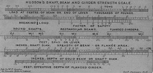
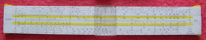
Fig. 1, The Front (Peter Fox)
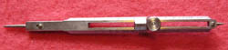
Figure 1 shows the front side of Peter Fox’s card example. As with the other scales, it has two slides. It measures 4½ inches by 2 1/8 inches and is contained in a slip case that is probably leather. The reverse contains tables and other information and is illustrated in Figure 2. This includes factors for converting the results to other materials or configurations.
Returning to Figure 1, let us assume that we wish to calculate the maximum safe load for a wrought iron beam, breadth 4 inches, depth 6 inches and span 8 feet. First set the breadth on the bottom slide against the depth on the bottom stator. Next set the WI mark (wrought iron) under the rectangular beam bracket on the upper slide against the span on the lower slide. Now read the breaking load off the upper stator and the maximum safe load off the upper stator adjacent to the desired factor of safety. Doing this with a replica I made from Peter’s scans, for the example, results in a breaking load of 60,000 pounds and, for a safety factor of 4, a maximum safe load of 15,000 pounds.
Now the maximum bending moment in a beam with a point load in the centre is W.L/4 where W is the point load and L is the length of the beam. In this case, taking the breaking load this equates to a maximum bending moment of 1,440,000 in.lbs. The maximum bending stress (tensile in the bottom face of the beam and compression in the upper face) is M/Z where M is the maximum bending moment and Z the section modulus, which is given by B.D²/6 where B and D are the breadth and depth of the beam respectively. This calculation results in a maximum bending stress of 26.8 tons/in². The table on the reverse gives the ultimate tensile strength of wrought iron as 22.5 tons (sic) and the ultimate crushing strength as 17 tons (sic) so the scale seems to give a result for the breaking load (it will fail in compression at the upper face) that is 57% too high in this case. However the formulae I have used are simple ones and I chose a relatively short beam (length 12 times depth) for which they might give an optimistic result so I doubled the length to 16 feet. The result for the breaking load was then given by the scale as 30,000 pounds or exactly half the previous one, so the scale is based on simple beam theory also.
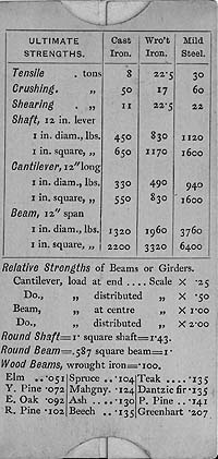
Fig. 2, The Reverse (Peter Fox)
However there appear to be other inconsistencies between the two sides of the scale since the three gauge marks for cast iron, wrought iron and mild steel on the front face do not give the same ratios between tensile strengths as those in the table on the reverse. Further calculations by Peter Fox have shown even more inconsistent and incorrect results. Perhaps, if we had the instructions, these differences could be resolved but we are inclined to think that the reason this rule is now so rare is that it was useless. My guess is that the engraver for the printing put the gauge marks on the lower face of the upper slide in the wrong positions. Was it produced for nearly 20 years without this being corrected and if so why?
As in the case of the pump duty computing scale, the earliest reference I have found is the 1890 edition of Stanley’s ‘Surveying & Levelling Instruments’ and the latest is the 1912 Stanley catalogue. It was presumably still available in 1918 as the 1918 price list (updating the 1912 catalogue prices) does not say it is no longer available. The card version in its case was priced at six shillings in 1898 & 1900, five shillings in 1912, which would have advanced by 66 2/3% to 8/4d in 1918. An opaque celluloid version was priced at fourteen shillings in 1912 and this would have advanced to £1 3s 4d in 1918.
I wonder whether examples were made in other materials besides those (card and opaque celluloid) shown in the references I have seen. This is the case with both the Pump Duty Computing Scale and the Horsepower Computing Scale, so it is quite possible.
So, thanks to Peter Fox, one more mystery has been solved. It now remains for someone to find an example of the Photo Exposure Scale, only known so far from an advertisement in the 1903 edition of Pickworth.
References:
1. David M Riches, Hudson’s Computing Scales, Slide Rule Gazette Issue 10 Autumn 2009, pp109-116
Other references are listed in the above referenced paper.
| Early Sets |
| Traditional Sets |
| Later Sets |
| Major Makers |
| Instruments |
| Miscellanea |
| W F Stanley |
| A G Thornton |
| W H Harling |
| Elliott Bros |
| J Halden |
| Riefler |
| E O Richter |
| Kern, Aarau |
| Keuffel & Esser |
| Compasses |
| Pocket compasses |
| Beam compasses |
| Dividers |
| Proportional dividers |
| Pens |
| Pencils |
| Rules |
| Protractors |
| Squares |
| Parallels |
| Pantographs |
| Sectors |
| Planimeters |
| Map Measurers |
| Miscellaneous |
| Materials Used |
| Who made them |
| Who made these |
| Addiator |
| Addimult |
| Other German |
| USA |
| Miscellaneous |
| Microscopes |
| Barometers |
| Hydrometers & Scales |
| Pedometers |
| Other instruments |
| Workshop Measuring Tools |
| Catalogues & Brochures |
| A Collectors Tale |
| Abergavenny Instruments |
| Spring Design Rule |
| Sperry Sonar Calculator |
| Thornton 6039 1/2 |
| Hudson slide rules |
| Hudson continued |
| Lambeth HP Calculator |
| Sterling Slide Adders |