


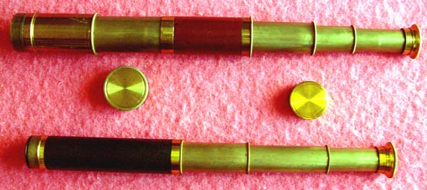
Two unsigned pocket telescopes described below
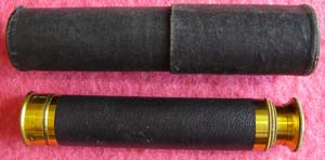
Three draw telescope with leather covered outer tube, pull-off objective cover and sliding eyepiece cover. Length overall 15.3”, closed 5.6”; objective diameter 0.9”. Cloth case.
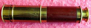
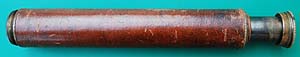
Three draw telescope with mahogany veneer covered outer tube, objective lens hood, pull-off objective cover and sliding eyepiece cover. Length overall 18.6”, closed 6.1”; objective diameter 1.1”.. English, probably ca.1900.
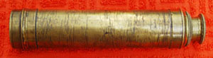
Unsigned three draw telescope (missing cover to outer tube and objective lens cover). Sliding eyepiece cover. Length overall 16.9”, closed 6.2”; objective diameter 1.2”. Battered but still working.
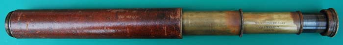
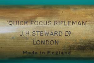
“Quick Focus Rifleman” telescope by J H Steward Ltd of London. A two draw telescope shown partially open and closed, signed on the inner draw. Length overall 23¼”, closed 11½“. Objective diameter 1.25”. Missing lens hood but in good working order.
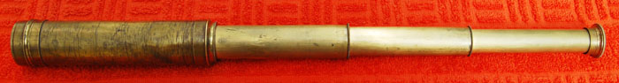
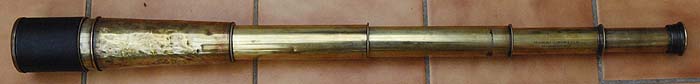
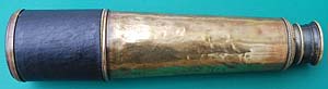
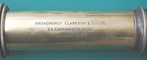
Broadhurst Clarkson & Co Ltd, 63 Farringdon Road, London EC four draw telescope, 33” long overall (36” with hood extended). Objective diameter 2 3/8”. Four powers marked on eyepiece draw: 25, 30, 35 & 40 times magnification. Leather missing from outer tube which is quite battered. Bright and very powerful scope. Probably ca.1900.
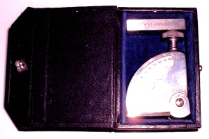
The Shore Instrument & Mfg Co, Jamaica, NY, USA “Durometer” Type A hardness tester for rubber, serial no 10031 with rubber support and blue velvet lined case.
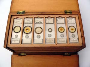
Pine box of microscope slides with twelve trays, each of six slides (72 slides total). Mostly professionally prepared Histology slides (of plant sections). Four trays by Abraham Flatters, 16 & 18 Church Road, Longsight, Manchester; four trays by A J Galloway, Salisbury. Odd slides by Richard Suter, 10 Highweek Road, Tottenham; J H Steward, 406 Strand, London.
Flatters was born in 1848. He was making microscope slides at 16 Church Road from 1895 to 1901, when he went into partnership with Charles Garnett.
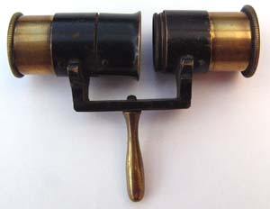
A hand held polarimeter, the two optical tubes each have a lens at each end and a Nicol prism in between. Neither rotates; it is in fact a ‘Pebble Tester’ for distinguishing ‘pebble’ lenses from glass ones. ‘Pebble’ was the optician’s name for rock crystal. Whilst holding the tester to the light, rotating a pebble lens between the two tubes would cause the light to disappear whilst glass would have no effect. These were marketed by J Raphael & Co, 51 Clerkenwell Riad, London EC, priced at 10s 6d post free in 1899.
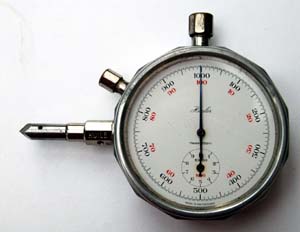
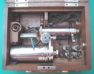
L S Starrett, Atholl, Mass., USA speed indicator, patented April 19th 1897. Used for measuring the speed of rotation of shafts in machinery, such as lathes. Unlike the instrument above, which has a built in stop watch, this had to be used in conjunction with a separate stop watch. Early 20th century.
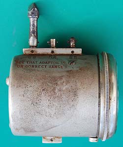
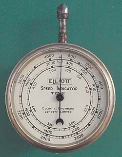
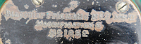
Elliott Bros speed indicator no. 23181. Depending on where the adapter is attached it has three speed ranges: 100-500; 400-2000; 800-4000 rpm.
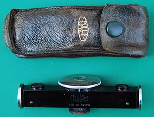
Pullin Optics rangefinder and leather case. The rangefinder has a large dial in the centre which is rotated to bring the two images into coincidence, when viewed through the eyepiece, which is in the centre on the opposite side to the dial. The range (from 1½ ft to infinity) can then be read from the dial. Length overall 3.4”, baseline 2.4”. Originally the property of a civil engineer, it is not clear whether he used this for his work or as a photographic rangefinder. Serial number 471126.
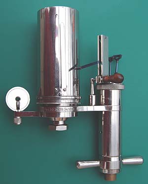
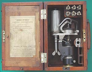
A ‘Tabor’ steam engine indicator made by The Ashcroft Manufacturing Co., Bridgeport, Ct, USA serial no. 5686. Patented Dec. 10th 1878 and Nov. 24th 1885. It has a comprehensive set of accessories including five piston springs (20, 24, 30, 40, 60), a spare drum spring, cord for attaching to the engine crosshead (via a reducing lever), oil bottle, two screwdrivers and four scales by Dobbie McInnes. The latter are contained within a tray that fits in the box. It would have been supplied with two engine cocks but these would have been fitted to the cylinder of the engine and remained there to allow the indicator to be removed when not required. There would also have been a pack of 100 cards to go on the drum but these would have been used, and a screwdriver which is missing. It is also missing the 300 page book that would have been supplied with it. However these are items that one would expect to have been used or misplaced in its life and it is in excellent condition, being about 100 years old. From the diagram produced the mean effective pressure in the cylinder could be found and the indicated horsepower calculated.
IHP = Pm.L.A.N/33000 where Pm = mean effective pressure, L= piston stroke, A=piston area, N=engine rpm. This would be measured for each cylinder, the values added together being the engine IHP. If the cylinders were double acting (admitting steam to both sides of the piston) then the sum would need to be multiplied by 2 to give the IHP unless each end of the cylinder was measured separately.
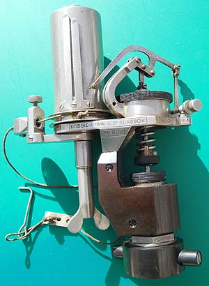
A Dobbie-McInnes No. 1, Large Size, engine indicator for engine speeds up to 250 rpm. It is housed in a mahogany box with six further springs, a spare drum spring and a spanner. Unlike the indicator above which has the pressure resisting spring located within the cylinder, this indicator is of the external spring type and the spring can be clearly seen between the piston and the straight line mechanism for the pen. As above the instruction book and charts are missing. It dates from the early twentieth century. Serial no. D 1A 16152.
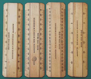
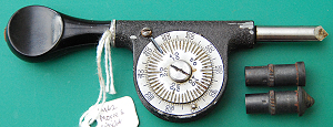
Cotton type Rangefinder Mk II no 1186 by E R Watts & Son. This instrument was used to measure the distance of an object from the observer. A 4" long linear concave lens (in cross section front and rear of the glass are parallel) is fixed to the base. A prism is mounted on a carriage with an index mark that slides back and forth along the axis of the instrument. When at infinity the slanted side of the prism is parallel to the corresponding part of the concave lens and cancels out any light breaking. A distance to an object can be measured when the height (or width) of the object is known. The carriage is slid until both ends of the object coincide, similar to the use of a stadimeter or sextant. Three reversible brass inserts calibrated on both sides in distance in yards, corresponding to various base heights, (20 and 25 feet, 30 and 35 feet and 40 and 50 feet), are fitted along the axis of the instrument. When the scale for the appropriate base height is selected and inserted, the carriage can be slid for coincidence and the distance read at the index mark on the sliding carriage. It is still in it's original mahogany box. Used by a master mariner in WWI.
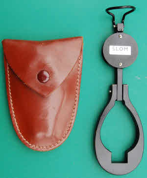
Distance finder by SLOM, Paris. Viewing through the edge of the black circular part with the name on a ground glass screen can be seen. When viewed close up there are three scales: on the left a % scale reads from -400 to 400; in the centre a scale reads from infinity to 10m downwards with a base of 1.7m (height of man in French alongside) and from infinity to 7m upwards with a base of 2m (placed at a height of 2m in French alongside); on the right a scale reads to 25 grads in each direction from a centre zero. When viewed at arms length, suspended from the thumb loop at the top, the centre scale is magnified and the distance to an object can be read from the centre scale. It appears that it can also be used as a clinometer. I would like to know more about this instrument and its maker.
The first two telescopes were an impulse buy, cheaply, at an auction. I was given the Durometer by a friend. The microscope slides came with my first microscope (the late 19th century drum type field one), and the polarimeter was purchased, not knowing what it was, for a tenner. After that I just found other interesting things to collect.
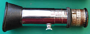
Hasler SA, Berne, Switzerland workshop tachometer for measuring the speed of rotation of lathe shafts, etc. and also for checking cutting speed. Serial No 91936. Mid 20th century. Complete with case, accessories, instruction leaflet and table of cutting speeds. Sold by “SIC” (Swiss Instruments & Components Ltd., 54 Cheam Common Road, Worcester Park, Surrey).


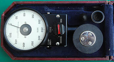
Smith’s Industries tachometer. A direct reading instrument with three settings, for 500, 5000, and 50,000 rpm. It has two cone adapters, inside and outside for shaft ends and a wheel for surface speed reading. It is missing an extension bar. It has a Blue velvet lined Morocco case with instructions in the lid.
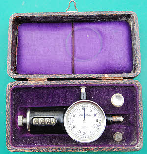
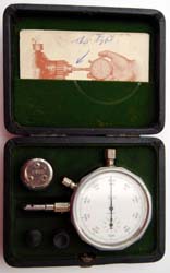
“Probator”, made in Germany, revolution counter used in conjunction with a stop watch to measure rotational speed of machinery. It has two attachments for the shaft point. The dial is zeroed by the pushing the button at the top and the digital counter is zeroed by turning the knob at the left hand end. These could be used up to 6,000 rpm.
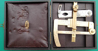
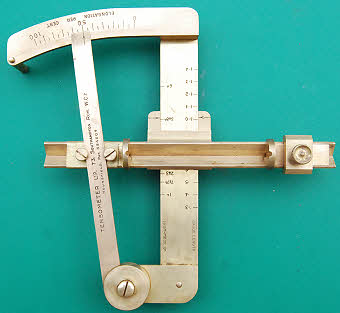
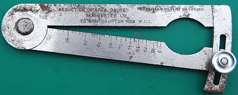
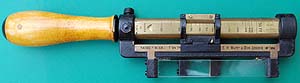
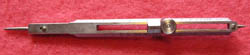
Tensometer Ltd, Southampton Row, London Extension and Reduction of Area Gauges. These are used to measure the elongation and reduction in cross sectional area of tensile test specimens The left hand, steel gauge measures the reduction in area (possibly the necking) of the test piece. It is first set by placing the specimen against the zero mark, closing the instrument on it and locking it with the screw. After test the test piece is then slid down the V until it stops and the % reduction area can then be read off the scale. The extension gauge is a little more complex. First the horizontal V section bar is positioned so that its index mark coincides with the test piece type or dimension and locked (the screw is underneath).Next the test piece is placed between the jaws and the right hand jaw is brought up to hold the test piece and clamped, whilst the pointer arm is set to zero on the arc scale. The test piece is then removed for the test after which it is returned to the space between the jaws that are opened to receive it by moving the pointer arm. If that is now brought hard up to the test piece the extension can be read off the arc scale.
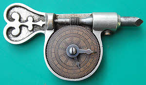
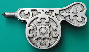
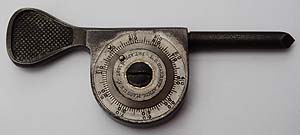
Ornate revolution counter used for determining shaft rotational speeds. Probably ca.1900 and similar to the ‘Woodman’ patent of 1876. Cast nickel-silver body & copper alloy face. Steel spindle, worm & hands.
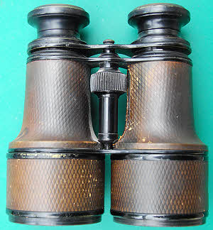
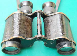
Binoculars of the Galilean type dating from the late 19th century or early 20th. They have central screw focusing and extending ray shades. They are black japanned brass with a thin tooled leather covering. The Galilean type have just two lenses, an eyepiece and objective They are unsigned.
DREM Justophot extinction exposure meter made in Austria. It has an instruction book and leather case. In use one of four exposure times is selected using the knurled ring - a corresponding number is llluminated by the reflected light from the subject. The inner most metal ring is rotated until the number disappears and then in the other direction until it is faintly seen and the aperture is read off against the index. By using the other two metal rings different combinations of exposure time and aperture can be selected. Instructions dated 1929.
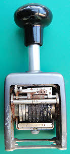
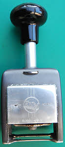
ENM model 4513 Automatic Numbering Machine. The machine can be set to a number of modes. The first is “repeat”, i.e. continue printing the same number each time the machine is operated by pushing down the black handle. The second mode is “consecutive” when it will add one to the number each time it is operated. The three remaining modes are “Duplicate”, “Triplicate” and “Quadruplicate” when it will print each number two, three and four times respectively before incrementing. It can print any six digit number. Numbers with fewer digits can either be printed with leading zeros or blanks. 4 1/2 mm figure size. Complete with instructions.
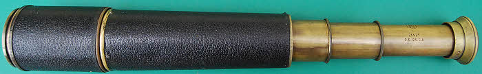
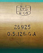
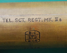
WWII British army spotting telescope “TEL. SCT. REGT. MK. IIs” (Scout Regiment Telescope) made by Broadhurst Clarkson & Co Ltd, serial no. 26925. A three draw telescope with 2” object glass and a magnification of 20x, length extended with ray shade as shown in the partially extended view 30”. Often used as the spotting telescope by sniper parties, it was very highly regarded and continued in use long after the war had ended.
Speed indicator by Moore & Wright with two rubber adaptors. Ca.1950s.
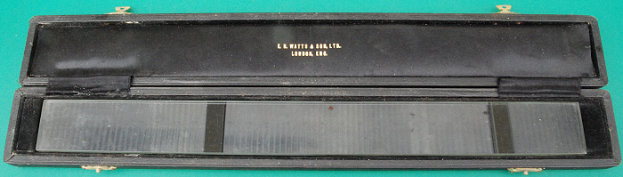
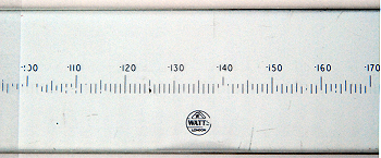
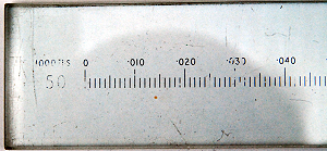
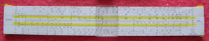
E R Watts & Son Ltd glass scale rule. The scale is thousandths of an inch times 50,
from zero to 0.250 inches. I think this scale was intended for use with a projectorgraph
or cabinet projector (refs: The Microscope, Beck, p.190 fig,142; Engineering Metrology,
Hume, p.110 plate 14). This is essentially a projection microscope for examining
small items such a screw threads in a workshop at a variety of magnification settings
from 10 to 100 times. An image of the item is projected onto a ground glass screen
at the desired magnification and this rule would have been used to measure the item
at a magnification of 50 times on the screen.
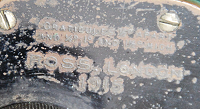
British army WWI binoculars. Marked on the faces adjacent to the eyepieces as follows:
Graticules ½° apart and ½º, 1º and 1½º high
Ross, London 1915
Binocular Prismatic No2 MkII Magnification 6 No 1852
The graticules are no longer visible.
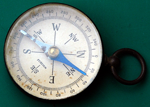
Small brass compass marked “Foreign”, 35mm diameter, probably 1920s/30s, possibly
made in Germany.
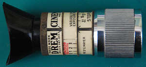
DREM Cinemeter made in Austria patented by Dr E Mayer. This is a simplified version
of the Justophot (see earlier on this page) for use with ciné cameras. It is an extinction
type of meter.
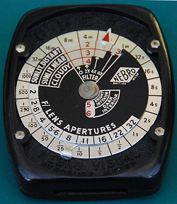
NEBRO Visual Exposure Meter. NEBRO was Neville Brown & Co Ltd, 71 Newman Street,
London W1. This extinction meter is complete with red card box and instruction book.
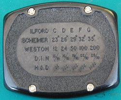
To use it the red arrow is first set to the Ilford speed letter for the film in use
( the reverse has a
table of equivalent film speeds). Pointing at the subject & looking through the slit
the highest easily read figure is selected & the top disc is rotated until that figure
in red is opposite the light conditions printed on the disc. Lens aperture can then
be read against exposure.
Inside the meter is a step wedge of neutral density filters, increasing in density
step by step. The more light that is reflected by the subject, the greater the density
of the step it can penetrate & the higher number that can be seen.
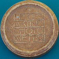
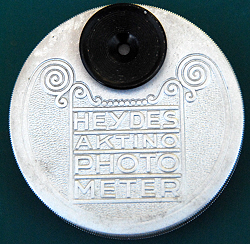
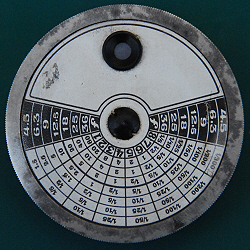
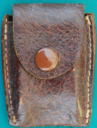
HEYDE’S AKTINO-PHOTOMETER made by G Heyde of Dresden, Germany. It is housed in a
moulded card case and is complete with instruction leaflet. To use the subject is
viewed through the eyepiece and the outer knurled rim is rotated until the subject
darkens. On the reverse of the instrument in the column opposite the arrow the shutter
speed is selected against the chosen aperture in the outer, black columns. For film
speeds other than H&D 200 the times had to be factored. The operating principle is
the same as for the NEBRO but the wedge is circular and rotates.
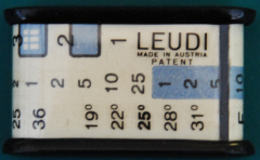
LEUDI patent exposure meter made in Austria by Ernst Pless patented by Alois Leber
in 1933. The varying translucency wedge is viewed through the slit and the least
readily visible number is read. The outer, transparent sleeve is then rotated until
the number is placed in the appropriate weather conditions box. The aperture can
then be read against shutter speed. This will be for a Scheiner film speed of 25º.
By rotating the sleeve it can be adjusted to other film speeds.
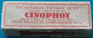
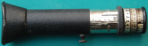
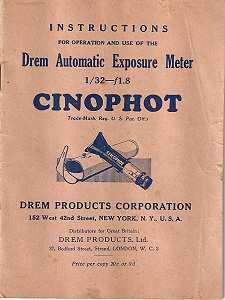
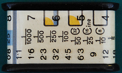
DREM Cinophot number 34604 with instructions dated 1931 and made in Austria (in-spite
of the wording on the box).
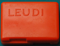
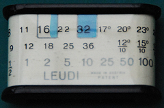
Another LEUDI meter complete with orange plastic case. This version has both Scheiner
and DIN film speeds listed with Scheiner 26º as the baseline and it does not feature
the cine frame rates listed on the one above.
Practos Junior. These were made by Hans Tönnies, Hamburg, Germany. Production started
in 30's and went on to late 50's.
The eye-piece shows a range of shutter speeds; the least distinct is correct for
a set aperture of f6.3 and film speed of 2700 H&D for other values the shutter speed
shown is set on the centre scale against the film speed, the shutter speed and aperture
pairs can then be read on the barrel. The inner tube is withdrawn by the eyepiece
to focus.
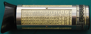
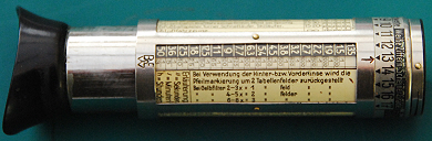
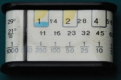
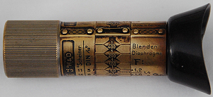
Figure 1 shows the Bewi Senior extended to focus & showing the transparent window
over the exposure field adjacent to the aperture field on the rotating sleeve and
also showing the filter factor adjustment table. Figure 2 shows the depth of field
table for three different focal length lenses. The other two faces show important
features and suggested exposures for different subjects.
Looking through the eyepiece a blue tinted aperture, through which the subject can
be seen, is surrounded by an arc of numbers. Before use it has to be focused on the
numbers by withdrawing the eyepiece and inner tube. Next the Scheiner film speed
needs to be set using the outer rotating band (the film speeds are the ‘white’ on
black numbers on this band) to set the speed against the red dot on the instrument
rim. It will click into place. Looking at the subject the highest visible number
is noted and then the arrow on the outer edge of the rotating sleeve is set to that
number on the outer rotating band. Next to that arrow the transparent window shows
the exposures that can be used with the adjacent apertures and a suitable pair can
be chosen. If a filter is fitted then the sleeve should be rotated back by the appropriate
number of increments (from the table) before the exposure/aperture pair is selected.
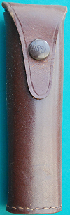
The meter has a brown leather case . It dates from ca.1930 and was made by Bertram,
Munich, Germany. An English language version was introduced in 1932. It cost £1 16s.