

Previously published in the Bulletin of the Scientific Instrument Society No.120, March 2014
Introduction
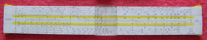
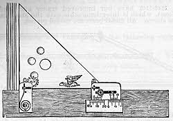
Firstly I guess I may need to explain what a section liner is since it’s hardly the most common of drawing instruments, at least here in the UK. Quite simply it’s an instrument for drawing closely and, most importantly, regularly spaced parallel lines such as those used by mechanical engineers and draughtsmen to illustrate a section through an item. Figure 1 is an example.
Fig. 1
This picture, from a Queen & Co catalogue of 1883 showed that, besides section lining (also known as cross-hatching), it could be used to depict screw threads (it shows two different methods) and shading of parts such as shafts, bolt shanks and oblique nut faces. Queen & Co also claimed it could be used to produce regular lettering, and by architects to draw brickwork.
However this figure also shows just how much more elaborate Victorian draughtsmanship was than present day practice for working drawings. Shading and colouring are no longer used, except for a rebirth in 3D CAD, and screw threads are depicted in a much simpler manner.
In spite of being a mechanical engineer by profession, both producing my own engineering drawings and working closely
with draughtsmen in the enormous design offices of the British Aircraft Corporation (later British Aerospace) at Filton I can’t recall ever seeing one of these devices in use and I didn’t even know of their existence until I started collecting old drawing instruments in the 1990s. Any self-respecting draughtsman would be quite capable of producing regularly spaced parallel lines with a set square or with his drafting machine set to the appropriate angle without the need for a special instrument. Hence the second part of my title. None-the-less an amazing variety of section liners were produced. Quite when the first ones appeared, however, is something I have yet to discover.
Simple Designs
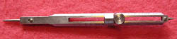
The simplest designs are based on the bar-type parallel rule and the set square and can be traced back to Victorian times. Figure 2 shows a parallel rule based example, The maker of this one is unknown but a similar one is shown in the A G Thornton catalogues of 1895 and 1916. Loosening the thumb screw enables the piece with the V cut into the end to be moved to set the spacing, the parallel rule then being stepped in the usual way. If the piece is removed altogether then it can be used as an ordinary parallel rule. This example is 12 inches long.
Simple Designs
The simplest designs are based on the bar-
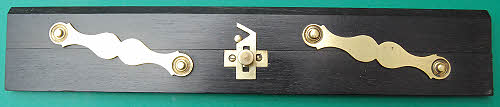
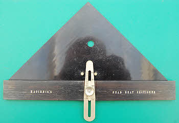
Fig. 2
Fig. 3
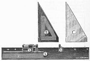
Figure 3 shows a Maginnis’s Dead Beat Sectioner, an example of a set square based instrument. The triangle is Vulcanite, the rule is ebony and the movable tapered tongue is electrum. This item is graduated for the space between parallel lines and it can be adjusted by sliding once the thumb wheel is loosened. There was some controversy over the naming of this instrument. W F Stanley, in the 1900 edition of his book on drawing instruments calls it Professor Honey’s section ruler and the version illustrated is a little different in that the tapered tongue and mounting slide are fitted to the triangle and the two pins are fitted to the rule. Stanley says “This
instrument appears to have been simultaneously invented by Mr J P Maginnis, but as Professor Honey had the earliest publication, his name is retained”. However others did not necessarily agree. Halden, in their ca.1925 catalogue, illustrate a different version of the “Maginnis” Dead Beat Sectioner that is shown in Figure 4. Only five set spacings could now be selected - I suspect this was cheaper to manufacture than the original form. The illustration also shows spacing examples. This design also appeared in a Harper & Tunstall catalogue dating from the 1930s. W F Stanley & Co Ltd also showed this design with a celluloid triangle in their 1912 catalogue.
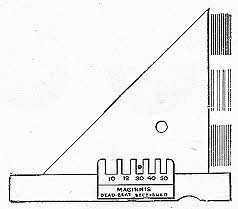
Fig. 4
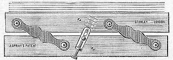
Fig. 5
Returning to the bar type of parallel rule, Aspray’s Patent Section Ruler, seen in Figure 5, was a more sophisticated version of that shown in Figure 2. A loop-piece fixed to the lower bar passed over a stud on the upper bar. The screw fixed to the loop piece could be used to adjust the open length of the loop, thus adjusting the relative movement of the two bars and hence the line spacing.
More Triangles
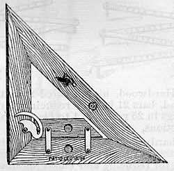
The Queen & Co catalogue of 1883i featured both Harden’s Im,proved Section Liner and Cylindrical Shader (seen in Figure 6) and Bergner’s Patent Section Liner (Figure 7). Two versions of Harden’s instrument were shown, the right hand one being adjustable for section lining only, whilst the left hand one could be adjusted to produce the graduated lining required for cylindrical shading.
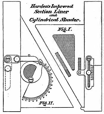
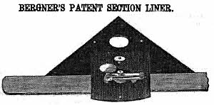
Fig. 6
Fig. 7
Bergner’s instrument consisted of a ruler with India rubber on the underside, to hold it in position, and a triangle with a plate projecting over the top of the ruler, containing the indexing mechanism. The triangle was held against the ruler edge by a spring. The mechanism, adjustable for line spacing, used a sharp pawl, engaging with the top surface of the ruler, to advance it when the ivory button was pushed down and allowed to spring back.
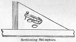
Fig. 8
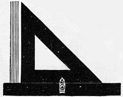
Fig. 9
William Ford Stanley described a somewhat similar instrument (Figure 8) in the 1878 and 1900 editions of his book on drawing instrumentsiii. The line spacing could be adjusted by the screw. Pressing down on the lever caused a chisel like foot to bite into the paper and advance the triangle the desired distance. It was returned by a spring. Whilst Queen & Co had described Bergner’s section liner as easy to use, Stanley was more honest, saying “There is a good deal of knack in using this instrument effectively. It has a disposition to slip through slight carelessness.”
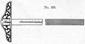
The 42nd edition of Gurley’s manual and catalogue lists several section liners including Marions’s (Figure 9). It is not described but appears to be similar to Maginnis’s in principle. This type of section liner was also shown, with several others, in the 1913 Keuffel & Esser catalogue where it was called “William’s Section Liner”. In the Keuffel & Esser version the triangle was made of transparent Xylonite and the rule of boxwood.
In the same catalogue Keuffel & Esser also advertised Hill’s Section Liner seen in Figure 10. The width of the spacing could be adjusted by
rotating the cam shown pivoting on the upright member of the triangle. Enlarging the woodcut reveals a US patent date of 18th December 1894. Hill’s Combination Section Liner and Triangle was also sold by the Technical Supply Co.. The same design was also listed by Gebr. Wichmann in 1939.
Fig, 10
Fig. 11
Casey’s Section Liner, shown in Figure 11, was also described in the 1913 Keuffel & Esser catalogue. The Xylonite triangle moved alternately with the boxwood rule a distance regulated by the electrum vernier scales to an accuracy of 1/100th inch or 1/10th of a millimetre.
A much later Keuffel & Esser catalogue (1949) only includes a much simplified “Section Liner Triangle” (Figure 12). The shuttle had four differently chamfered corners so that, by inserting it different ways round, four different line spacings could be achieved. The triangle was made of transparent material and its simple construction meant that it had the advantage of being reversible. This instrument was still listed in the 1955 Keuffel & Esser catalogue
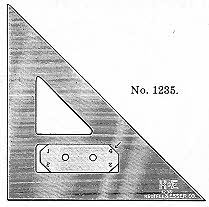
Fig. 12
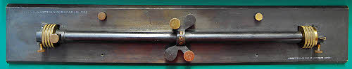
Fig. 13
More Parallel Rule types
Rolling parallel rules were the basis of a number of section liner designs and the Stockman & Doyles’ Spacing Parallel, shown in Figure 13, is an example. It was sold by J Short, 2 Gladstone St, Southwark, London. By the left hand wheel is a thumbscrew that is used to lock the sleeve to the spindle when the spacing mechanism, seen in the centre, is in use. The mechanism rocks the sleeve and hence rotates the spindle to provide the space between the parallel lines. The spacing distance can be set using the two thumb screws by the rocking levers. A scale on the right hand wheel enables the spacing distance to be accurately set. The body of the 15” instrument is blackened brass. It has a mahogany box.
Rolling parallel rules were the basis of a number of section liner designs and the Stockman & Doyles’ Spacing Parallel, shown in Figure 13, is an example. It was sold by J Short, 2 Gladstone St, Southwark, London. By the left hand wheel is a thumbscrew that is used to lock the sleeve to the spindle when the spacing mechanism, seen in the centre, is in use. The mechanism rocks the sleeve and hence rotates the spindle to provide the space between the parallel lines. The spacing distance can be set using the two thumb screws by the rocking levers. A scale on the right hand wheel enables the spacing distance to be accurately set. The body of the 15” instrument is blackened brass. It has a mahogany box.
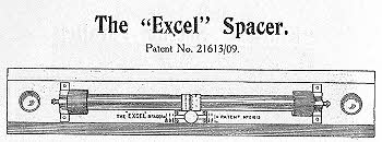
Fig. 14
The “Excel” Spacer (Figure 14) was listed in the A G Thornton catalogue for 1916ii. The description reads “Made in solid metal with rolling wheels running in adjustable centre. In the centre of the spindle carrying the rolling wheels, a third wheel is fixed on which various sets of divisions are cut of equal distance apart, the usual being 1/16”, 1/10”, 1/8”,
¼”, ½”, 1”, but other spaces can be divided if required. A moveable slide with carrying and spring feeding point is fixed on the base of the rule opposite the divided wheel, and the portion of the base over which the slide moves is marked with lines and figures to correspond with the dividing of the centre wheel. By placing this slide at the spacing required, and setting the rule in motion the spring feeding point catches on the divisions in the centre wheel and is slightly checked at the correct intervals or divisions to correspond with the spacing required. The divided wheel is turned back in the centre so that when the slide is set central on the base, the rule may be used as an ordinary parallel.”
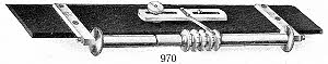
The E O Richter catalogue for 1928 shows two types of sectioning parallel, each of which could be purchased in a variety of materials. The 970 (Figure 15) had five centre wheels, each notched to give a different spacing. The spring pointer/index was mounted on a slide so that it could be moved to engage with the notches on any of the wheels. If moved out of engagement the the instrument would function as an ordinary parallel. It is also shown in the Gebr. Wichmann catalogue of 1939ix.
The E O Richter catalogue for 1928 shows two types of sectioning parallel, each of which could be purchased in a variety of materials. The 970 (Figure 15) had five centre wheels, each notched to give a different spacing. The spring pointer/index was mounted on a slide so that it could be moved to engage with the notches on any of the wheels. If moved out of engagement the the instrument would function as an ordinary parallel. It is also shown in the Gebr. Wichmann catalogue of 1939ix.
Figs. 15
& 16
& 16
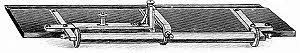
Figure 16 shows the other type of Richter spacing parallel, that was also listed in the 1897 catalogue. This type was sold by other makers in Germany as well as in Britain and the USA. Figure 17 is from a Friedmann catalogue. It is also shown in the 1916 A G Thornton catalogueii in which its operation is described: “This instrument is easily operated without practice and with absolute accuracy. By means of an adjusting screw in the centre of the spring lever the distance required between each line is first set, then by simply pressing upon the set screw on the top of the moveable lever, equal spacing is obtained after each line is drawn.” Other sellers of this type of spacing parallel included Ecobra, Wichmannix, and NYB (1916).
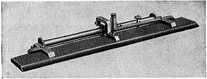
Fig. 17
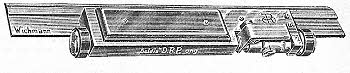
Fig. 18
The 1939 Wichmann catalogue also listed the *Goldis” DRP section liner (Figure18) made by E O Richter. The spacing between lines could be varied between 1 and 20 mm. The instrument was made of nickel silver and was 225 mm long.
Another Triangle Type
The System Krakau section liner (Figure 19) was another type listed in the 1939 Wichmann catalogueix. It was a new instrument at that time and had alternative metal and clear plastic triangles. It was intended for lithographic work. The metal rule was 270 mm long.
Fig, 19
Figs. 20a
& 20b
& 20b
Section Liners with Inclinable Rules
These section liners have the advantage that parallel lines can be drawn at a range of closely controllable angles. Whilst this might also be said of the parallel rule types they are inclined to wander or slip in even the most skilled hands and they do not have an in-built facility for setting to a designated angle. Although some inclinable rule types were produced in the 19 th century they did not become the predominant type until the second half of the twentieth.
These section liners have the advantage that parallel lines can be drawn at a range of closely controllable angles. Whilst this might also be said of the parallel rule types they are inclined to wander or slip in even the most skilled hands and they do not have an in-
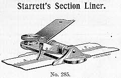
Starrett’s section liner was described in the International Correspondence Schools cataloguex and comprised a mechanism and inclinable rule to be used with the Starrett T square. This T square could be supplied with an engraved scale, which the mechanism would ratchet along, the throw being regulated by an adjusting nut. The rule could be set to any angle.
The 1908 Gurley Manualviii showed a rather complex, rack and pinion instrument (Figure 21). The rack-rod passed through two heavy weights and was held securely by two clamp screws and the weights were held in place by two needle pointed pins. Lines could be drawn at any angle, in any direction, and on any part of the board. two plain notched wheels were supplied with each instrument for producing 64 and 100 parts to the inch. Extra wheels for other values from 10 to 50 parts per inch could be supplied.
The 1908 Gurley Manualviii showed a rather complex, rack and pinion instrument (Figure 21). The rack-
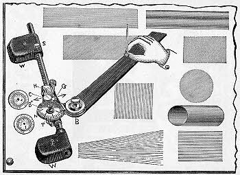
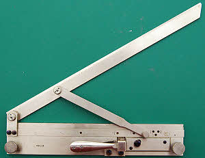
Fig. 21
Fig. 22
The Riefler section liner (Figure 22) is believed to have first been produced in 1894 and this example is certainly pre-WWI. It is made of nickel-silver. It was still being produced in 1939 when it appeared in the Wichmann catalogue xi at which time the inclining rule could be supplied in either nickel-silver or Plexiglas. At 54 RM it was 2½ times the price of any of the other section liners. The rule can be inclined at a variety of angles and it is actuated by depressing the lever. which moves a pin that drives the rack forward. Curiously the spacing is set by the angle of inclination of the rule. Thus with the rule vertical the spacing is one rack tooth = 1½ mm. At the least inclination it is just ¼ mm. There are screw down pins to hold the base plate in position on the board.
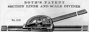
Fig. 23
Both’s Patent Section Liner and Scale Divider was catalogued by Keuffel and Esser in 1913ix and continued too appear in K&E catalogues until at least 1936. It was ade of German Silver with a base length of 14¾ inches. The protractor was graduated in degrees with a Vernier reading to 5 minutes. The rack and pawl mechanism could be adjusted so that the pawl advanced the ruler arm from one to six teeth. There were 21 teeth to the inch on the rack. Pressing the knob caused the rack to advance. It was another very expensive device. Gurleyviii and Eugene Dietzgen Co were also sellers of Both’s instrument although the latter did not call it Both’s.
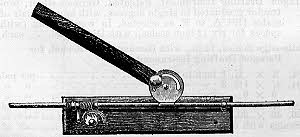
Fig. 24
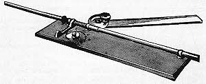
Fig. 25
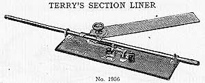
Fig. 26
Also in the 1913 K&E catalogue was this “Simplex” section liner (Figure 24). The mechanism was a very simple one, but also very effective and many later instruments used the same mechanism. The rule, via its angle setting plate, was attached to a rod that slid through two bearings on the base plate. The rod had a helical spring around it at the left-hand end of the base plate with a lever pushing against it. When the lever was pushed to compress the spring the rod was driven forward by friction. The spacing was set by the cam that limits the travel of the lever. Figure 25 shows a similar instrument sold by H Cole Co. and similar instruments were also sold by Dietzgen xvii, B K Elliott Co., and other American suppliers at least until the 1940s.
Terry’s Section Liner, patented on July 14th 1891 and July 17th 1906 was sold by the New York Blue Print Paper Co.xvi The ‘positive’ mechanism is not described and is not clear from the woodcut. A version was also sold by W & L E Gurley.
Terry’s Section Liner, patented on July 14th 1891 and July 17th 1906 was sold by the New York Blue Print Paper Co.xvi The ‘positive’ mechanism is not described and is not clear from the woodcut. A version was also sold by W & L E Gurley.
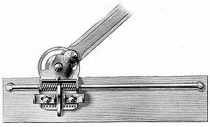
Fig. 27
Figure 27 shows the “Favorite Reversible Section Liner” from the 1921 New York Blue Print Paper Co catalogue. This was another spring actuated instrument but the rod was fixed and the mechanism and ruler were mounted on a carriage. Two springs were used, one for each direction and separately adjustable for spacing, with the actuating lever between them. As with some of the other types of section liner this was also available from other suppliers including B K Elliott Co.
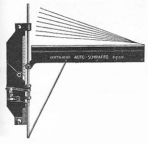
Fig. 28
The “Auto-Schraffo” was listed by Gebr. Wichmann xi in 1939. It was another spring actuated device but was more robustly constructed with metal base plate and rule (edged with celluloid) and some parts stainless steel or chrome plated. The illustration shows that it could be used to draw radial lines as well as parallel ones. As with other spring actuated section liners the line spacing adjustment was in the form of a screw that limited the travel of the actuating lever.
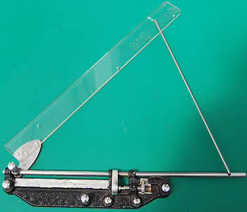
Fig. 29
The “Golmet Auto-Liner”, made in England and patent pending, (Figure 29) appears to be a copy of the instrument above. It has a clear plastic rule and the base plate is cast aluminium with a black crackle finish. There are three, screw-down pins to hold the instrument in place and the spacing adjustment screw is notched and locked by a U shaped spring underneath. It possibly dates from the 1950s
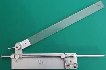
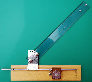
Fig. 30
Fig. 31
The Kern section liner (Figure 30), made in Aarau in Switzerland, is yet another spring operated device and merits little further description. It probably dates from the third quarter of the 20th century. The rule is acrylic whilst the remaining parts are metal.
Figure 31 shows an Alpe “Super Velox 300” section liner. The 30 cm ruler can be set to angles of 0, 15, 30 and 45 degrees and the line spacing can be adjusted between 0.5 and 4 mm. The arm and ruler are advanced by pressing the button on the left hand side of the mechanism cover. Made of wood, metal and plastic, probably in the 1960s. Friction mechanism. Italian. Complete with card box and instruction leaflet (in Italian).
Discussion and Tentative Conclusions
Since the second half of the nineteenth century many designs of section liner have been created. I do not know when the first was designed or produced and I am sure that there are many more designs than I have shown here. As I have not yet carried out a patent search, I am sure, from my experiences with searches for other types of drawing instrument, that there are many patents for designs that were either never made or never proceeded beyond the prototype stage. That remains a task for the future.
I have tried to group the instruments by type, apart from a couple of early examples, and it seems logical to me that the first section liners evolved from existing instruments, such as the set square (triangle) and the parallel rule, which could be used to draw section lining anyway. However the real step forward was the type I have called the inclinable rule type as this allowed both the spacing and angle to be set with some precision. This seems to be the only type that remained popular into the second half of the twentieth century.
From examining early twentieth century catalogues it is apparent that section liners were much more popular in the USA, and possibly Germany, than in the UK. Whilst the death of many types of mathematical instrument may be attributed to increasing computer sophistication and usage it seems to me that, in the UK at least, the section liner had died many years before. Why? I think one explanation may be the progressive simplification of mechanical drawing through the middle of the twentieth century in accordance with the British Standard BS308. The engineering drawing had become purely functional and was no longer a piece of art. Design engineers and draughtsmen no longer needed section liners.
I would welcome any further information on these devices.
Notes and References
i. Price And Illustrated Catalogue of Mathematical Instruments: And Materials For Drawing, Surveying, And Civil Engineering (1883), James Queen And Company, reprint by Kessinger Publishing, p67.
ii. Drawing Surveying & Scientific Instruments and Drawing Office Materials, A G Thornton Ltd, Manchester, 1916, p327. It was branded here as the “Kinwest” Section Parallel and was available in six different lengths from 6 inches at 3s/3d to 24 inches at 8s/9d. In the 1895 catalogue it was simply known as “Thornton’s Improved Sectioning Parallel” and prices were slightly lower at 2s/9d to 7s/6d.
iii. Mathematical Drawing, and Measuring Instruments, their Construction, Uses, Qualities, Selection, Preservation, and Suggestions for Improvements, with Hints upon Drawing, Colouring, Calculating, Sun Printing, Lettering, &c., William Ford Stanley, 7th edition, E & F N Spon, 1900.
iv. J Halden & Co catalogue, ca.1925, p135.
v, Catalogue, Harper & Tunstall Limited, 1930s, p45. The “Sectioner Set Square” is not attributed to Maginnis (or anyone else) in this catalogue.
vi. W F Stanley & Co Ltd catalogue, 1912, p47. The same items also appeared on p288 of the 1931 catalogue. However the ca.1946 W F Stanley catalogue did not show any section liners.
vii. Aspray’s Patent Section Ruler appears in the 1900, seventh edition, of W F Stanley’s book on drawing instruments (iii) and in the 1912 and 1931 W F Stanley & Co Ltd catalogues (vi).
viii. A Manual of the Principal Instruments used in American Engineering and Surveying, W & L E Gurley, Troy, NY, USA, 42nd edition, August 1908. Besides Marion’s section liner it also lists Casey’s Section Liner, Terry’s Positive Section Liner and Both’s Section Liner and Scale Divider as well as a ‘Standard Section Liner’ for school use and two section liners of the adjustable angle type (described and illustrated later In this paper). The 1874 21st edition only lists Bergner’s and Queen’s in addition to Marion’s.
ix. Catalogue of Keuffel & Esser Co, 1913, New York
x. Illustrated Catalogue and Price List Drawing Instruments and Appliances, Drawing Papers and Materials, Surveying Instruments, Mining Instruments, Anemometers, Safety Lamps, Etc. Presented at Premiums to Students of the International Correspondence Schools, Scranton, PA. Undated early 20th century, p42. The triangle was stated to be made from cherry wood.
xi. Gebr. Wichmann Haupt-Katalog 20 Ausgabe, Gebr. Wichmann, Berlin NW7, 1939. By this time Wichmann were largely sellers of instruments made by other firms, and it is doubtful that they made any of these section liners in-house. Three types they sold were by Richter, whilst another was made by Riefler. The firm was founded in 1873 and was probably the largest retailer of mathematical instruments in Germany with an enormous range described in this 778 page catalogue.
xii. K&E Catalog Drafting and Reproduction Equipment and Materials, Slide Rules, 41st Edition Part 1, Keuffel & Esser Co, October 1949, p129.
xiii. Katalog der Präzisions=Reisszeugfabrik E O Richter & Co., Chemnitz, 1928
xiv. Friedmann Bros. Precision catalogue, Friedmann Bros. Drawing Instrument Co., New York, 1935/1939.
xv. Bayerische Reisszeugfabrik A G vorm. Eichmüller & Co. Nürnberg 28, Preis-liste Ausgabe 1929.
xvi. Catalogue of Drawing Materials & Engineering Instruments, NYB, New York Blue Print Paper Co, New York, 1916.
xvii. Catalog of Eugene Dietzgen Co., Thirteenth Edition, Chicago, 1928
xviii. H Cole Co. Catalogue No. 4D, Columbus, Ohio, undated but ca.1930
xix. B K Elliott Co. Drawing Materials and Surveying Instruments, 6th Edition, November 1938, Pittsburgh, PA.
xx. Catalog of New York Blue Print Paper Co., New York, 1921.
ii. Drawing Surveying & Scientific Instruments and Drawing Office Materials, A G Thornton Ltd, Manchester, 1916, p327. It was branded here as the “Kinwest” Section Parallel and was available in six different lengths from 6 inches at 3s/3d to 24 inches at 8s/9d. In the 1895 catalogue it was simply known as “Thornton’s Improved Sectioning Parallel” and prices were slightly lower at 2s/9d to 7s/6d.
iii. Mathematical Drawing, and Measuring Instruments, their Construction, Uses, Qualities, Selection, Preservation, and Suggestions for Improvements, with Hints upon Drawing, Colouring, Calculating, Sun Printing, Lettering, &c., William Ford Stanley, 7th edition, E & F N Spon, 1900.
iv. J Halden & Co catalogue, ca.1925, p135.
v, Catalogue, Harper & Tunstall Limited, 1930s, p45. The “Sectioner Set Square” is not attributed to Maginnis (or anyone else) in this catalogue.
vi. W F Stanley & Co Ltd catalogue, 1912, p47. The same items also appeared on p288 of the 1931 catalogue. However the ca.1946 W F Stanley catalogue did not show any section liners.
vii. Aspray’s Patent Section Ruler appears in the 1900, seventh edition, of W F Stanley’s book on drawing instruments (iii) and in the 1912 and 1931 W F Stanley & Co Ltd catalogues (vi).
viii. A Manual of the Principal Instruments used in American Engineering and Surveying, W & L E Gurley, Troy, NY, USA, 42nd edition, August 1908. Besides Marion’s section liner it also lists Casey’s Section Liner, Terry’s Positive Section Liner and Both’s Section Liner and Scale Divider as well as a ‘Standard Section Liner’ for school use and two section liners of the adjustable angle type (described and illustrated later In this paper). The 1874 21st edition only lists Bergner’s and Queen’s in addition to Marion’s.
ix. Catalogue of Keuffel & Esser Co, 1913, New York
x. Illustrated Catalogue and Price List Drawing Instruments and Appliances, Drawing Papers and Materials, Surveying Instruments, Mining Instruments, Anemometers, Safety Lamps, Etc. Presented at Premiums to Students of the International Correspondence Schools, Scranton, PA. Undated early 20th century, p42. The triangle was stated to be made from cherry wood.
xi. Gebr. Wichmann Haupt-
xii. K&E Catalog Drafting and Reproduction Equipment and Materials, Slide Rules, 41st Edition Part 1, Keuffel & Esser Co, October 1949, p129.
xiii. Katalog der Präzisions=Reisszeugfabrik E O Richter & Co., Chemnitz, 1928
xiv. Friedmann Bros. Precision catalogue, Friedmann Bros. Drawing Instrument Co., New York, 1935/1939.
xv. Bayerische Reisszeugfabrik A G vorm. Eichmüller & Co. Nürnberg 28, Preis-
xvi. Catalogue of Drawing Materials & Engineering Instruments, NYB, New York Blue Print Paper Co, New York, 1916.
xvii. Catalog of Eugene Dietzgen Co., Thirteenth Edition, Chicago, 1928
xviii. H Cole Co. Catalogue No. 4D, Columbus, Ohio, undated but ca.1930
xix. B K Elliott Co. Drawing Materials and Surveying Instruments, 6th Edition, November 1938, Pittsburgh, PA.
xx. Catalog of New York Blue Print Paper Co., New York, 1921.
| Early Sets |
| Traditional Sets |
| Later Sets |
| Major Makers |
| Instruments |
| Miscellanea |
| W F Stanley |
| A G Thornton |
| W H Harling |
| Elliott Bros |
| J Halden |
| Riefler |
| E O Richter |
| Kern, Aarau |
| Keuffel & Esser |
| Compasses |
| Pocket compasses |
| Beam compasses |
| Dividers |
| Proportional dividers |
| Pens |
| Pencils |
| Rules |
| Protractors |
| Squares |
| Parallels |
| Pantographs |
| Sectors |
| Planimeters |
| Map Measurers |
| Miscellaneous |
| Materials Used |
| Who made them |
| Who made these |
| Addiator |
| Addimult |
| Other German |
| USA |
| Miscellaneous |
| Microscopes |
| Barometers |
| Hydrometers & Scales |
| Pedometers |
| Other instruments |
| Workshop Measuring Tools |
| Catalogues & Brochures |