

In fact, searching the index, I found 79 in the name of W F Stanley and I already had a copy of one US patent of his. Not all of these were instrument patents and I will mention some of the others in due course. Of the 79 listed in the index, 26 could not be found, mostly because they were abandoned or void, but in at least one case the number in the index appears incorrect. All 79 from the index are listed in Appendix A. Whilst one can look at the patent specifications in the British Library they cannot be copied there. The later ones (from ca. 1895) can be downloaded and printed from the espacenet web site whilst copies of the remainder have to be ordered from the Intellectual Property Office. In general the date quoted is that of the application.
This patent was intended to cover the use of aluminium in all sorts of geometric drawing, surveying and nautical instruments. However the claim appears to really cover the use of a steel plate in the centre and steel washers between other mating surfaces in sector and knee joints to avoid the soft aluminium wearing. He also claimed this improvement to apply to other metals.
This patent was far more significant and actually included a number of unrelated devices; in all, five claims:
1. An instrument for drawing large radius arcs based on the same principle as a centrolinead.
2. Compasses having crossing or converging stay rods between the legs to keep them parallel.
3. Spring bows with knee joints and the adjusting screw below the knee joints, to the points perpendicular to the drawing surface.
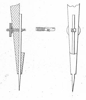
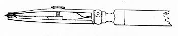
4. Securing the needle of a compass by passing it through a hole in a bolt drawn tight by a nut (later known as Stanley’s type B point or a ‘nut and bolt needle point’. (Fig.1)
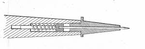
5. A spring loaded needle point for compasses (later know as Stanley’s type A point). (Fig.2)
Stanley provided both the types of needle point in his highest quality sets and the nut and bolt type (claim 4) became virtually a universal standard once the patent expired.
(Patent GB1863/226)
Optical compass (Mathematical Drawing Instruments, W F Stanley, 1900)
This patent also included five claims:
1. An improvement to the geometrical pen to produce hypocycloid and epicycloid curves.
2. An improvement to the instrument used to draw conchoid curves by changing the bed from an inverted L shaped one to a T shaped one. The instrument could also be used as a semi-
4. The addition of two mirrors to as pair of compasses, functioning in the same way as the mirrors on a sextant, together with an eyepiece to give the perspective position of objects by reflection, such that they can be transferred directly to a drawing (Fig 4).
5. A variant of the optical compass described in 4 where the legs are parallel bars.
Drawing Boards, Straight Edges, &c, 1870 (15th August) No. 2264
This patent was concerned with the use of metal reinforcing to drawing boards and other wooden drawing apparatus to resist the unequal contractile forces in the wood. The metal reinforcing could be through the wood across the grain or at the edge where it could also form a sliding or drawing edge. Various embodiments of this were illustrated.
Where rods were inserted through several boards they could be threaded at the end and used to clamp the boards together. Stanley’s ‘Portable Drawing Board’, as shown in the 1912 catalogue, incorporated this feature. Metal reinforcing bars, as described elsewhere in this patent were also used in Stanley’s ‘Patented Steel Lined Drawing Boards’, quoted as ‘suitable for tropical climates’.
Points for Mathematical Drawing Instruments, 1874 (2nd February) No. 412 (Provisional only)
The use of steel wire, soldered in a prepared groove, as the point for a compass or dividers. I have never seen this type of point in a drawing instrument or even in a catalogue or book. Was it ever used in practice?
Colours, 1877 (12th September) No. 3438
This patent related to the use of colours for tinting drawings, a practice that was standard at the time. There were three claims:
1. Colours, diluted with water to a state ready for use, with details of the colours to represent different materials.
2. Naming the colours with the names of the materials they would represent.
3. Placing the colours in bottles labelled with the name of the represented material and with the actual tint enamelled or varnished into a recess in the top of stopper.
The filed drawing was partly coloured, presumably with 24 tints as there are 24 named boxes (stone, brass, etc.) on the copy of the drawing.
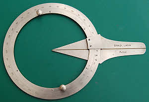
This patent was for a circular protractor with two concentric rings, one rotating within the other, each having a straight edge attached to it that terminated in a point at the centre.
Stanley sold this instrument as his ‘Reading to Centre Protractor’. The vernier read to minutes. Fig. 5 shows the example in my collection.
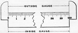
This patent covered the use of small inset scales, away from the main scale edge, for use with divider points to avoid damaging the main scale (Fig, 6). Stanley catalogued these scales, at least up to 19124. The patent also covered the method of attachment.
Improvements in Dotting Pens, 1887 (24th June) No. 8985
The patent describes the use of an inner blade to feed ink to the rowel wheel of the pen. (Fig. 7)
This invention was described in several forms. However the main feature was that the jaws were shaped to match that of a typical dip pen nib so that they would clamp on it without damaging it for its extraction.
This was also patented in the USA; patent no. 479,959 dated August 2nd 1892.
This was a joint patent with Alfred Amsler. It related to the use of a small vernier scale on the arm of an adjustable planimeter to enable the planimeter to be adjusted to give a true reading of area from shrunk plans where the shrinkage could be determined by measuring the scale drawn on the plan (Fig. 8). It was catalogued in 1912 as the ‘Stanley Amsler Patented Compensating Planimeter’.
Improvements in Combined Drawing Board and Tee Square for Geometrical Drawing, 1895 (8th August) No. 15,023
This was a joint patent with Joseph Charles Howard. The stock of the tee square was arranged to slide in a groove at the edge of the board and a lever-
Improvements in Drawing Boards and Tee Squares, 1898 (28th October) No. 22,710
Another joint patent, this one with Robert William Fieldwick. This was a simpler patent covering the use of projecting, inset metal edges to both the board and tee square stock, where the two metal edges slid in contact with each other. These were made with a brass tongue to the tee square stock and a gunmetal edge to the board, 1912 catalogue numbers K3295, 3296 and 3297.
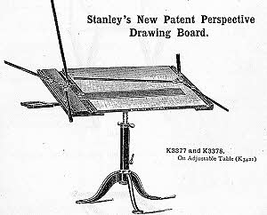
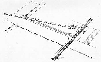
The patent describes a board mounted on a stand, such that it can be raised to any height and tilted to any angle, that incorporates a tee square, running in a groove and lockable by a lever and cam arrangement, and also right and left centrolineads, mounted at the edges. The latter are arranged with a hinged blade so that it can be lifted clear of the board.
This was also shown in the 1912 catalogue when it was available in two sizes at £4 and £4 10s respectively. (Fig. 9).
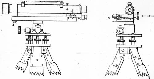
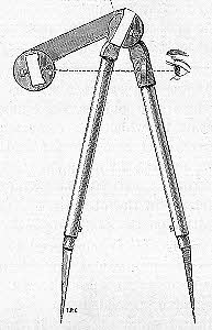
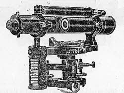
This patent covered a set of equipment for determining distance by triangulation from near and distant bases. The base line was established by a steel wire extended between either two vertical rods (distant base), or between two telescopes (near base). The telescopes could be mounted on a or hand held The steel wire (for near base triangulation) was attached to each telescope such that it directed its axis, so that when the telescope was turned to the distant object or rod, the angle could be read directly in the eyepiece. For triangulation using a distant base, the steel wire was stretched between two vertical rods and a single telescope was used to measure the angle between them. In this case the telescope required to be mounted on a stand and set up in the same manner as the lower part of a theodolite and the baseline had to be at right angles to the line from one of the rods to the telescope. The telescope is illustrated in Fig, 10.
Improvements in Mining Stadiometers, Theodolites and Tacheometers, 1889 (9th August) No. 12,590
The purpose of this invention was to enable mining instruments to be used conveniently in workings with severely restricted headroom. The improvements were in two related parts:
1. A folding stadia rod for subtense measurements or levelling
2. Any mining instrument used for subtense measurements with the stadia, in which the compass was illuminated from below by a lamp and mirror
3. A tribrach with a sliding stage for accurate centring of the instrument
4. Screw up adjustment of the tripod legs
Improvements in Apparatus for Measuring Distances, 1890 (8th March) No. 3683
This was essentially a special form of stopwatch set in motion when a flash was observed and stopped when the associated sound was heard. It could be calibrated in distance (or time). The version illustrated was mounted on the stock of a rifle. Although this patent can be read in the British Library the IPO were unable to supply a copy of it.
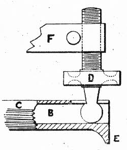
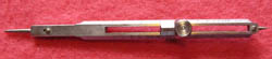
This patent covers the use of longitudinal holes to retain the ball ends of the tribrach adjusting screws instead of a retaining plate. This arrangement was used on many Stanley theodolites. (Fig. 11)
Fig 11 -
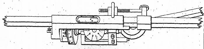
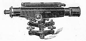
This was a form of tilting level with a screw inside a screw inside a graduated drum enabling it to be used for reading or indicating gradients in elevation or depression from 1 in 12 to 1 in 1,200 although this range was not stated in the patent. This was Stanley’s ‘Patent Gradiometer’, which was also fitted with a subtense diaphragm for measuring distances. (Fig. 12).
Improvements in Mining Surveying Instruments, 1898 (20th April) No. 9134
This patent covered two solutions to the problem of taking readings at high angles of depression with surveying instruments in mines without the use of an auxiliary telescope:
1. A mirror in front of the object glass, set accurately to take readings at 90 degrees to the line of collimation of the telescope.
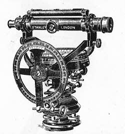
2. A cranked gimbal ring on a mining dial to enable the telescope to be set at 90 degrees up or down whilst clearing the support structure. This featured in ‘K301 Stanley’s New Patent Dial’ and K304 ‘Stanley’s 6 inch Cranked Gimbal Dial (Patent)’ in the 1912 catalogue (Fig. 13)
The purpose of this invention was to enable all the readings to be taken from the face of the instrument without requiring access to the sides for reading the vernier plates as would be the case with an ordinary theodolite, thus enabling its use in confined spaces, for instance in mines.
To achieve this the patent had a number of features:
1. A rack and gear train to a series of dials to indicate the precise rotation about the horizontal and vertical axes.
2. For distance measurements by stadia or subtense reading telescopes, a diaphragm with compensating points giving direct base reading allowing for the difference between hypotenuse & base for inclination. The 1912 catalogue lists the ‘Patent Compensating Subtense Diaphragm’ as a separate item.
3. A means of adjusting the spirit level from the same face.
Although detailed as five claims there are really two significant improvements described in this patent:
1. The casting of the telescope body in one piece with the centre and also the long and cross bubble fittings.
2. The positioning of the internal focussing rack under the drawtube such that the pinion shaft could be supported at both ends.
“Improvements in straight-
The first improvement described is the use of a lead screw that is oblique to the line of the bed and for which the oblique angle could be varied to vary the distance travelled by the knife per revolution so that the scales of any country could be divided.
The second improvement was a means of making the dividing engine self-
The third improvement was a means of regulating the length of the lines divided onto the scale by means of a detent wheel with teeth of differing lengths corresponding to the line lengths required.
Typically a lever would be used and worked backwards and forwards to cut the lines to the required length, regulated by the detent wheel, and also to effect the rotation of the lead screw to give the distance between the lines as described in the second claim.
Meteorological Instrument, 1867 (25th November) No. 3335
Stanley’s ‘Meteorometer’ for predicting the probable weather. This combined a number of instruments on a single mount as follows:
|
·
|
An aneroid or preferably mercury barometer to show the air pressure, the mercury barometer having a float and vernier instead of an adjusting screw
|
|
·
|
A compass dial connected to a weather vane on a high point on the building connected by rods and Hook’s joints to show the wind direction
|
|
·
|
A manometer connected by a thin tube to the weather vane to show the wind force
|
|
·
|
Instruments to show the temperature, humidity and electric state of the atmosphere
|
|
·
|
An inverted barometer tube to indicate rising or falling pressure (but not the pressure itself)
|
|
·
|
A barometer wheel and index hand responding to the atmospheric pressure pointing to the words fair, rain, storm, etc on the dial which was rotated according to the wind direction
|
|
·
|
An indicator showing the rain fall in a given period connected to a rain gauge on the roof of the building
|
It could be ‘of ornamental construction, and be fixed in any gentleman’s hall.’
Machines for Exciting Frictional Electricity, 1868 (21st December) No. 3878
This was a hand held version of the plate glass electrical machine. The improvements claimed were:
1. A frame consisting of two strips of wood with a handle connecting them at one end and a spacing block at the other.
2. The exciting rubbers attached directly to the frame
3. A wood axle rather than metal
4. A sheet glass disc rather than plate glass
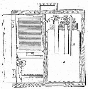
This invention was a portable electric battery. The battery described, with zinc and carbon plates, was essentially a Leclanché cell without the porous pot containing the manganese peroxide depolariser around the carbon electrode. However the purpose of the patent was not the method of generating the electricity but the means by which the battery was rendered portable and the description of the battery internals was purely illustrative. The claims were basically as follows:
1. The jar or bottle containing the electrodes would be twice the height internally of the electrodes and filled to half height with the electrolyte so that the electrodes were normally out of the liquid and the battery would need to be inverted for operation.
2. The cell would be sealed against liquid leakage but incorporate a relief valve to allow gases to escape.
4. A wooden box to contain the cells, packed in tightly with wool or other matter
5. The incorporation in the box of an electric bell or Ruhmkorff coil or other apparatus (Fig. 15)
6. The incorporation of this portable battery in fixed apparatus
Pendulums for Equalizing (sic) Pressure and Temperature and Calculating Time, 1875 (29th November) No. 4130
Integrating Anemometer, 1883 (7th February) No. 672 (Provisional only)
The purpose of this invention was to indicate in one operation both the velocity and direction of the wind. The axis of revolution of the anemometer cups was arranged to rotate around a second, principal axis by the action of the wind to a position opposite to the direction of the wind. A series of recorders, one for each wind direction would be placed around the periphery of the instrument. A crown wheel on top of each recorder would be rotated only when the axis of rotation of the cups was directly over it, when it would be rotated by a conoid under the axis of rotation of the cups with its axis at an oblique angle to the cup axis and connected to it by a Hook’s joint.
Stanley had a number of photography patents, mostly for camera improvements such as focussing methods. As cameras are not normally classed as scientific instruments I have omitted to describe them in this paper. However I have included this one as it is for a meter. It was a very short patent with two claims:
|
·
|
Enclosing the actinometer in a small round case similar to that used for a magnetic compass, that could be hung on a watch chain
|
|
·
|
Filling the actinometer with a paper made sensitive with a salt of Bromine.
|
The patent was joint with William Low Sarjeant
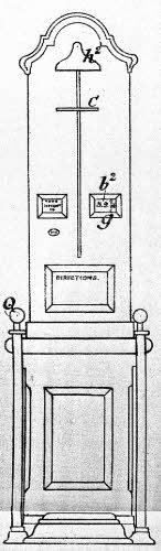
Improvements in Height Measuring Machines, 1887 (22nd August) No. 11,416
This patent claimed a number of improvements to the machine described in the previous patent.
|
·
|
Replacing the dial at the top of the instrument (too high to read easily) by a window nearer eye height, through which the height could be read on a disc revolving inside or a straight scale moving up and down inside.
|
|
·
|
The use of the straight scale as a counterbalance weight
|
|
·
|
Improvements to the mechanism used to return the index back to zero
|
|
·
|
Air cushioning of the counterbalance weights to prevent concussion & noise and ensure smooth operation
|
|
·
|
Improvements to the penny in a slot mechanism
|
|
·
|
Means to stop the head plate being pushed up from outside the case
|
Fig. 16 shows the general arrangement of the machine.
1. Coin operation and its associated mechanism
2. The delivery of a disposable cone or mouthpiece to fit on the mouth tube and the use of disinfectants, etc in connection with the machine.
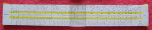
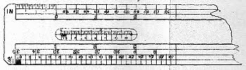
A slide rule basically consists of two parts, the stock and the slide. In this case there are one scale on the stock above the slide, two on the slide and five on the stock below the slide. These are, in that order:
|
·
|
A scale labelled A divided to give the square root of the fifth powers of the values on scale B
|
|
·
|
A scale labelled B divided for areas
|
|
·
|
A scale labelled 1 in divided for inclination
|
|
·
|
A scale for velocities
|
|
·
|
Four scales to correspond to four classes of channel and their coefficients, divided for hydraulic mean depth
|
On the reverse were instructions and tables giving area and hydraulic mean depth for full pipes and segments of circles and ovals.
The patent had two claims:
|
1.
|
The nature and layout of the scales and tables on the slide rule
|
This patent was joint with W F Stanley and Co Ltd.; the business had become a limited liability company in 1900 according to C J Allen.
A look at Appendix A will show that his inventions ranged far wider than instruments. Some were in related fields, such as photography and spectacles, but others related to such things as cooking and building, and even rotary engines.
From 1885 onwards, increasing numbers of his patents were either void or abandoned. I do not know why this was so. Was it because they didn’t meet the test of being new inventions or was it because he chose to abandon them?
2. Surveying and Levelling Instruments: Theoretically and Practically Described (1901), William Ford Stanley, 3rd edition, Kessinger Publishing reprint
3. A Century of Scientific Instrument Making 1853-
5. W F Stanley & Co catalogue, 33rd ‘A’ Edition, 1958
6. Slide Rules, Their History, Models, and Makers, Peter M Hopp C.Eng,MBCS, Astragal Press, 1999, ISBN 1-
|
Year |
Number |
Date |
Description |
|
1861 |
3092 |
10 Dec |
The use of aluminium for the construction of mathematical instruments used for geometrical drawing, surveying and nautical purposes, and improvements connected therewith |
|
1863 |
226 |
26 Jan |
Mathematical drawing instruments |
|
1863 |
1245 |
4 May |
Straight line dividing engines and tools for regulating distances |
|
1866 |
664 |
5 Mar |
Mathematical drawing instruments |
|
1867 |
3335 |
25 Nov |
A new meteorological instrument |
|
1868 |
3878 |
21 Dec |
Construction of machines for exciting frictional electricity |
|
1870 |
2264 |
15 Aug |
Construction of true surfaces and edges applicable to drawing purposes |
|
1872 |
2213 |
25 Jul |
Electrical apparatus |
|
1874 |
411 |
2 Feb |
Circular saw bench |
|
1874 |
412 |
2 Feb |
Mathematical drawing instruments |
|
1875 |
4130 |
29 Nov |
Clocks |
|
1877 |
3438 |
12 Sep |
Colours |
|
1880 |
2142 |
26 May |
Measuring distances |
|
1880 |
3253 |
18 Aug |
Photographic cameras |
|
1882 |
3268 |
10 Jul |
Photographic cameras |
|
1883 |
672 |
7 Feb |
An integrating anemometer |
|
1885 |
4528 |
13 Apr |
Photographic cameras |
|
1885 |
4529 |
13 Apr |
Actinometer for photography |
|
1885 |
4530 |
13 Apr |
Protractors |
|
1885 |
12953 |
28 Oct |
Buffers |
|
1885 |
15115 |
9 Dec |
Tooth injector |
|
1886 |
2701 |
24 Feb |
Chandeliers and pendants |
|
1886 |
2811 |
26 Feb |
Focussing arrangements for cameras |
|
1886 |
3357 |
10 Mar |
Knives |
|
1886 |
3990 |
22 Mar |
Heat conductors for cooking flesh quickly |
|
1886 |
3991 |
22 Mar |
Presses for rendering steaks tender |
|
1886 |
4624 |
2 Apr |
Actinometers for photography |
|
1886 |
4726 |
5 Apr |
Measuring height of human beings |
|
1886 |
5407 |
19 Apr |
Mathematical scales |
|
1886 |
10589 |
18 Aug |
Portable saws |
|
1886 |
13052 |
13 Oct |
Sinking surfaces of steel dies, stamps and punches by combined photographic and etching processes |
|
1887 |
3081 |
28 Feb |
Levels and clinometers |
|
1887 |
7244 |
18 May |
Heat conductors for baking and boiling |
|
1887 |
8985 |
24 Jun |
Dotting pens |
|
1887 |
9454 |
4 Jul |
Spectacles |
|
1887 |
11416 |
22 Aug |
Height measuring machines |
|
1887 |
13013 |
25 Sept |
Spirometers |
|
1888 |
259 |
6 Jan |
Explosives &c for producing instantaneous light for photography |
|
1888 |
10429 |
23 Jul |
Rangefinders |
|
1888 |
17078 |
23 Nov |
Writing pen extractor (also patented in USA) |
|
1889 |
12590 |
9 Aug |
Mining stadiometers |
|
1889 |
18735 |
|
Lemon squeezers |
|
1889 |
20493 |
|
Spectacles |
|
1890 |
3683 |
8 Mar |
Measuring distances |
|
1890 |
20493 |
27 Mar |
Slide rules |
|
1890 |
17445 |
31 Oct |
Portable photographic apparatus |
|
1891 |
8715 |
22 May |
Artificial horizons |
|
1891 |
12374 |
21 Jul |
Portable photographic apparatus |
|
1892 |
14934 |
18 Aug |
Instruments of precision |
|
1893 |
9274 |
9 May |
Mantles for incandescent lighting by gas |
|
1893 |
19812 |
20 Oct |
Combined drawing board and tee square |
|
1894 |
7099 |
10 Apr |
Compressing and refrigerating apparatus |
|
1894 |
13507 |
13 Jul |
Planimeters |
|
1895 |
6229 |
26 Mar |
Surveyor’s tools |
|
1895 |
15023 |
9 Aug |
Drawing board and tee square |
|
1896 |
15037 |
7 Jul |
Rendering candles &c wicks waterproof |
|
1896 |
16360 |
23 Jul |
Route indicator for vehicles |
|
1896 |
22476 |
10 Oct |
Tramcars, motor cars, &c |
|
1897 |
404 |
6 Jan |
Eyeglasses |
|
1897 |
2441 |
29 Jan |
Phonographs |
|
1897 |
19937 |
30 Aug |
Calculating apparatus |
|
1898 |
9134 |
23 Apr |
Mining surveying instruments |
|
1898 |
21396 |
11 Oct |
Advertising signs |
|
1898 |
22710 |
28 Oct |
Drawing boards &c |
|
1898 |
23130 |
3 Nov |
Representing life movements |
|
1899 |
7864 |
14 Apr |
Surveying instruments |
|
1899 |
18583 |
14 Sept |
Instruments of precision |
|
1900 |
1872 |
30 Jan |
Cameras |
|
1900 |
7664 |
25 Apr |
Camera dark slides |
|
1900 |
17838 |
8 Oct |
Rotary engines |
|
1901 |
2675 |
7 Feb |
Photographic cameras |
|
1901 |
18447 |
20 May |
Surveyor’s levels |
|
1902 |
19909 |
11 Sep |
Eye glasses |
|
1902 |
20222 |
16 Sep |
Fitting stone skirtings |
|
1903 |
18863 |
1 Sep |
Phonographs &c records |
|
1903 |
26382 |
2 Dec |
Telescopes |
|
1903 |
26754 |
7 Dec |
Standard measure gauges and rods |
|
1905 |
6167 |
23 Mar |
Drawing tables |
|
1906 |
649 |
10 Jan |
Rotary steam engines |
| Early Sets |
| Traditional Sets |
| Later Sets |
| Major Makers |
| Instruments |
| Miscellanea |
| W F Stanley |
| A G Thornton |
| W H Harling |
| Elliott Bros |
| J Halden |
| Riefler |
| E O Richter |
| Kern, Aarau |
| Keuffel & Esser |
| Compasses |
| Pocket compasses |
| Beam compasses |
| Dividers |
| Proportional dividers |
| Pens |
| Pencils |
| Rules |
| Protractors |
| Squares |
| Parallels |
| Pantographs |
| Sectors |
| Planimeters |
| Map Measurers |
| Miscellaneous |
| Materials Used |
| Who made them |
| Who made these |
| Addiator |
| Addimult |
| Other German |
| USA |
| Miscellaneous |
| Microscopes |
| Barometers |
| Hydrometers & Scales |
| Pedometers |
| Other instruments |
| Workshop Measuring Tools |
| Catalogues & Brochures |